Page 1 of 1
Simplified Wifi breakout board (pics)
Posted: Thu Feb 19, 2015 6:22 pm
by mx270a
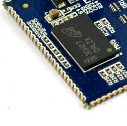
I wanted to incorporate the Wifi module into a future design, but I wanted to confirm that I had the right connections to make it work before rolling it in to a larger PCB. I ended up making a tiny PCB to connect just the necessary leads for a connection over SPI. Schematic and pictures are below. For use on SPI, mode0 and mode1 get pulled high.
I like the compact size of the Wifi module, but I'm not thrilled about not being able to see what the solder joints look like. Version 1 works great, so I guess my concern is unfounded.
-Lance
Re: Simplified Wifi breakout board (pics)
Posted: Fri Feb 20, 2015 6:58 am
by seulater
Glad you got it working. I am doing the same thing as well for my project. I too wish they would have chosen a different pad layout for the module. Something like this.

- 2015-02-20_8-56-39.jpg (17.65 KiB) Viewed 6242 times
Re: Simplified Wifi breakout board (pics)
Posted: Fri Feb 20, 2015 10:02 am
by dciliske
I agree with wanting the half-moon pads, but I'd guess that they would: a) add to the board cost, b) add slightly to the board size, and c) make it harder to do the trace antenna.
Also, Lance, MODE1 should be pulled high as well for SPI. In the current firmware, MODE1 is a "Don't care" for either mode, but is marked as "Reserved" for state 0. This is to allow us to add USB or other bus configuration at a later date (USB might be interesting due to fewer pins, but it'll be slower than SPI, as it will only be Full Speed (12Mbps)).
-Dan
Re: Simplified Wifi breakout board (pics)
Posted: Fri Feb 20, 2015 10:09 am
by mx270a
How do I check or update the firmware on the wifi modules?
I recall on a previous post some discrepancy between the jumper settings on the silkscreen and the quick start guide. There was mention of updating the firmware to have the silkscreen be correct.
Re: Simplified Wifi breakout board (pics)
Posted: Fri Feb 20, 2015 10:19 am
by dciliske
All SOMs have the correct firmware. It was only the first 5 adapter boards that had the issue (well, actually 1 SOM was shipped but then replaced in transit). I actually don't have a quick way to do that check at the moment...
As for the quickstart not matching the silkscreen, I misinterpreted the silkscreen vs. the schematic when finalizing the firmware for the first production run. The quickstart was written during this confusion. Currently, the adapter Schematic == adapter silkscreen == device firmware != quickstart.
-Dan
Re: Simplified Wifi breakout board (pics)
Posted: Mon Jun 29, 2015 7:22 pm
by seulater
dciliske wrote:I agree with wanting the half-moon pads, but I'd guess that they would: a) add to the board cost, b) add slightly to the board size, and c) make it harder to do the trace antenna.
Also, Lance, MODE1 should be pulled high as well for SPI. In the current firmware, MODE1 is a "Don't care" for either mode, but is marked as "Reserved" for state 0. This is to allow us to add USB or other bus configuration at a later date (USB might be interesting due to fewer pins, but it'll be slower than SPI, as it will only be Full Speed (12Mbps)).
-Dan
Dan, just a thought adding them would not add any more cost. you could keep the board the same size Just put the half moon pads at the very edge of you current pads. I do not see how it would affect the trace antenna section since there are no pads there.
This would allow many more people to be able to solder their own prototypes, and small run builds.